ray tracer
Introduction
The ray tracer works by casting rays from a point to a through a point pixel gird, corresponding to the colour of the pixel that the ray traced. This illumination model allows us to only consider the light reaching the camera. the recursive ray tracing that is implemented here allows for serval key features, the ability to render, transparent, refractive, and reflective properties. This is in conjunction with the ability to render, planes, spheres, cones, truncated cones, double cone, and cylinders with caps. The simulation takes roughly 1 minute and 10 seconds to render a 1000x1000 pixel grid with a max depth of 6, running on a ryzen 9 5900x.
Transparent & refractive object shadows
Both transparent and refractive object cast lighter shadows based on their coefficients and colors. This was done by checking to see if the closest object intersecting the point to the light source, was either transparent or refractive and not the object itself. If the object the shadow was being cast on to be the object that it was the closest intersection, as in if the objects were the same object, the transparent or refractive would end up with a shadow on it like a regular object, this would no look correct as a clear object should not have a shadow. Once this check was done it would deice how to color the point based on the color of the transparent or refractive object.
-
If the color of the object was black, then it would multiply the color of the point with either the transparentCoeff or refractionCoeff.
-
If the color was within the gray tones or white, as in if all RGB channels were equal, then the gray tone would be multiplied by the transparentCoeff or refractionCoeff and subtracted from the color at the point. The reason for this subtraction is that this would then move the value of the color at that point closer to zero, there for the color would become darker, showing that it is in shadow.
-
Finally, if the color was neither black nor gray/white, the color of the transparent or refractive is be multiplied by the transparentCoeff or refractionCoeff. Then each of the color channel of the object, has the max value of the RGB channels subtracted from it. This causes the value at that point that is in shadow to have a max value of the color that is going through the transparent or refractive object.
glm::vec3 c = sceneObjects[shadowRay.index]->getColor();
if (c == glm::vec3(0)){
    color *= sceneObjects[shadowRay.index]->getRefractionCoeff();
}else if (c.x == c.y && c.y == c.z){
    printf("c : %f\n", 1-sceneObjects[shadowRay.index]->getRefractionCoeff());
    color -= sceneObjects[shadowRay.index]->getRefractionCoeff()*c.x;
} else {
    c *= sceneObjects[shadowRay.index]->getRefractionCoeff();
    glm::vec3 c_max = glm::vec3(std::max({c.x, c.y, c.z}));
    color -= c_max - c;
}
This technique creates lighter shadows for transparent or refractive object while retaining the color that would be passing through them.
Texture mapping
There are two shape that are texture mapped, the sphere and cone. The sphere uses a simple algorithm of uv wrapping where points of the sphere are mapped to a 2d texture. this unwrapping is done by converting the hit location in from rectangular coordinates to spherical coordinates where:
Where n is the normalized vector of the hit subtracted from the center. Both are added by 0.5 to properly center it on the 2d image. As is returns numbers in the domain of . The texture mapping for the cylinder maps the curved portion of the cylinder to the 2d image and maps the top of the cylinder to the top of the 2d image.
Where h is the height of the cylinder. When mapping on to the top flat region of the cylinder the and . This maps the top of the cylinder to just the very top of the 2d image. This allows for an almost seamless texture mapping.
Cylinder
Intersections
The cylinders were created by find both t values that satisfy the equation for a vector intersecting a cylinder:
If the value of t was in the imaginary plane, then the vector did not intersect the cylinder. although this is the equation for an uncapped cylinder. To find the cap of the cylinder the values of t were checked, if was above the height of the cylinder and was below the height of the cylinder. then the vector was intersecting the top of the cylinder, with the value of t at that point being .
Normal
The normal of the cylinder is computed by the point where the normal is subtracted by the center. This is vector is then normalized by dividing the radius of the cylinder:
The y component is set to zero unless the vector is intersecting the top of the cylinder. This is because the normal does not change with differing values of y unless the normal is at the top of the cylinder. for calculating the normal at the top of the cylinder, the normal will remain constant no matter what values x, y, or z are therefor it returns
Cones
Intersection
The cones intersection is calculated in a similar fashion to that of the cylinder, expect for the cone will instead check its cut off points at its height limit value. This is done so one equation can be used for drawing truncated cones, normal cones and double cones. The intersection equation for the cone is:
Where r_2 equal to the radius over the height squared. With the same methods of finding valid values of t for where it intersects as well as if there is cap on the cone for if it is truncated or a double cone.
Normal
The normal for a point on a cone, is calculated by finding the length of the x and z components hit point on the cone and returning a normalized vector of:
And if the normal was being calculated for a cap the same method was used as the one outlined in the cylinder.
Sphere example:
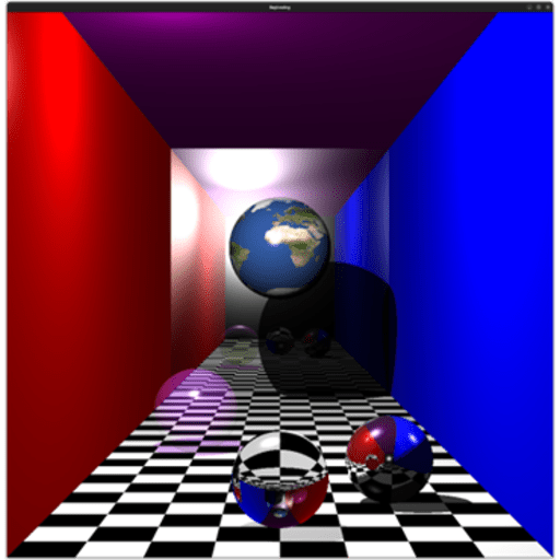
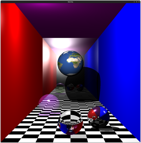 Figure 1: Sphere raytracing example
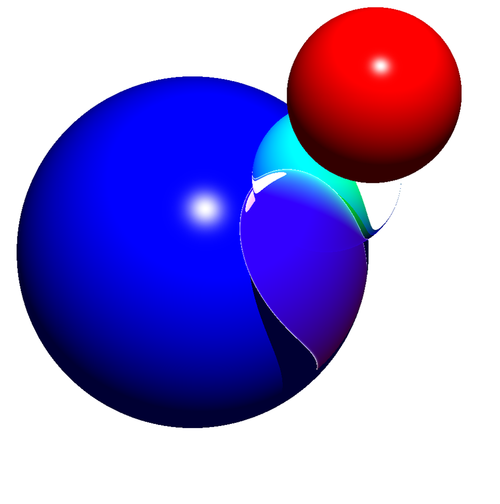
In this figure 4 spheres can be seen, 1 that has a texture map image of earth on it, a transparent purple one over to the left, a refractive in the center and finally a reflective sphere on the right. All these spheres also have specular reflections, as can be seen by the shiny spot on them.
As can be seen on the transparent purple sphere, the shadow cast by it is not only lighter but also, the same color as the sphere itself, using the method outlined in Transparent & refractive object shadows.
The refractive sphere in the center displays the image of the room but upside down. This is because the sphere has a refractive index of a . although it is hard to see the sphere casting a light shadow onto the ground.
In the reflective sphere on the right-hand side the refractive sphere can be seen through it refracting off the red from the left-hand wall.
Finally the larger textured sphere in the back center, is textured using the method in texturing, as well due to how it is implemented the textured sphere could also be transparent although this leads to incorrect lighting in the shadows.
Figure 1: Sphere raytracing example
In this figure 4 spheres can be seen, 1 that has a texture map image of earth on it, a transparent purple one over to the left, a refractive in the center and finally a reflective sphere on the right. All these spheres also have specular reflections, as can be seen by the shiny spot on them.
As can be seen on the transparent purple sphere, the shadow cast by it is not only lighter but also, the same color as the sphere itself, using the method outlined in Transparent & refractive object shadows.
The refractive sphere in the center displays the image of the room but upside down. This is because the sphere has a refractive index of a . although it is hard to see the sphere casting a light shadow onto the ground.
In the reflective sphere on the right-hand side the refractive sphere can be seen through it refracting off the red from the left-hand wall.
Finally the larger textured sphere in the back center, is textured using the method in texturing, as well due to how it is implemented the textured sphere could also be transparent although this leads to incorrect lighting in the shadows.
Cone example:
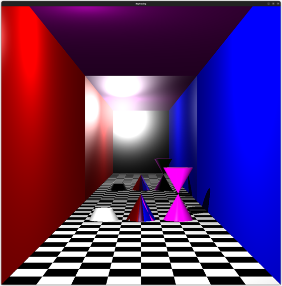 Figure 2: cone Example
As can be seen in figure 2, there are 3 cones, one truncated, one normal and reflective and one double cone. The top of the truncated cone appears to be white due to the light being from up high and the cone having specular reflections so the top would appear to be quite shiny. The center cone is reflective, and the double cone can be seen in its reflection to the left, as well as both walls. The double cone shadow can be seen clearly behind it.
Figure 2: cone Example
As can be seen in figure 2, there are 3 cones, one truncated, one normal and reflective and one double cone. The top of the truncated cone appears to be white due to the light being from up high and the cone having specular reflections so the top would appear to be quite shiny. The center cone is reflective, and the double cone can be seen in its reflection to the left, as well as both walls. The double cone shadow can be seen clearly behind it.
Cylinder example:
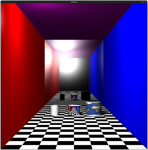 Figure 3: cylinder example
As can be seen in Figure 3 there are 3 cylinders, 1 white one, a reflective one in the center and one texture mapped one to the right. The within the center cylinder both white cone and texture mapped cylinder can be seen. The white cylinder as the same white top as the green cone as seen before due to the same reasons as well as the reflective cylinder reflecting all the light from the source above it.
the texture mapped cone can be seen with a white top corresponding the top of the texture.
Figure 3: cylinder example
As can be seen in Figure 3 there are 3 cylinders, 1 white one, a reflective one in the center and one texture mapped one to the right. The within the center cylinder both white cone and texture mapped cylinder can be seen. The white cylinder as the same white top as the green cone as seen before due to the same reasons as well as the reflective cylinder reflecting all the light from the source above it.
the texture mapped cone can be seen with a white top corresponding the top of the texture.
Experimental roughness/light bouncing
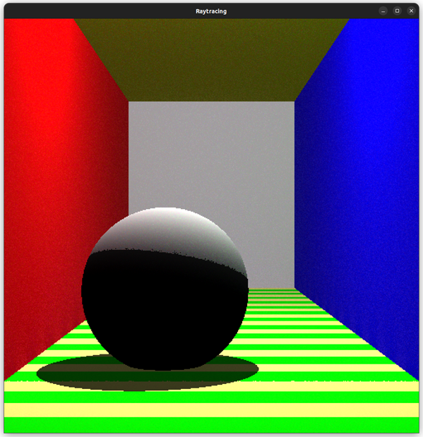 Figure 4: light bouncing experiment
The image as seen in figure 4 shows a rough pass, of having light scatter when hitting an object and sampling other objects with random vectors to simulate a more accurate version of reality. This can be seen more at the intersection of the left red wall and the striped ground, where the left wall is slightly colored by the light bouncing off the floor. Although not as noticeable the sphere can also be seen with a red tint on the left and a blueish tint on the right. This was very computationally expensive.
Figure 4: light bouncing experiment
The image as seen in figure 4 shows a rough pass, of having light scatter when hitting an object and sampling other objects with random vectors to simulate a more accurate version of reality. This can be seen more at the intersection of the left red wall and the striped ground, where the left wall is slightly colored by the light bouncing off the floor. Although not as noticeable the sphere can also be seen with a red tint on the left and a blueish tint on the right. This was very computationally expensive.
Mirror bouncing
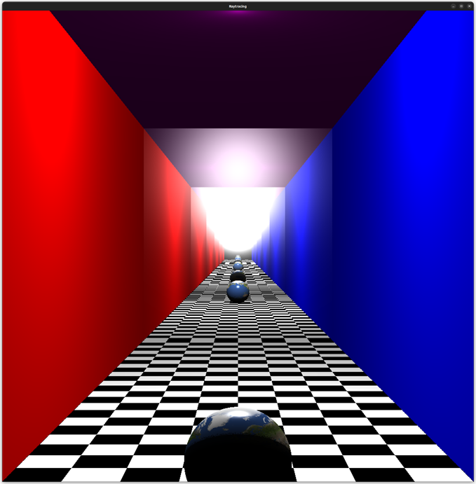 Figure 5: bouncing through mirrors.
Figure 5 depicts a room with 2 mirrors at either end with a model of the earth within it. The model earth can be seen to be repeated through all the mirrors within this room. A slightly more impressive example can be seen in appendix A
Appendix
These are a few of the cool test renders I had when developed the ray tracer.
A: album cover
B: album cover
C: album cover
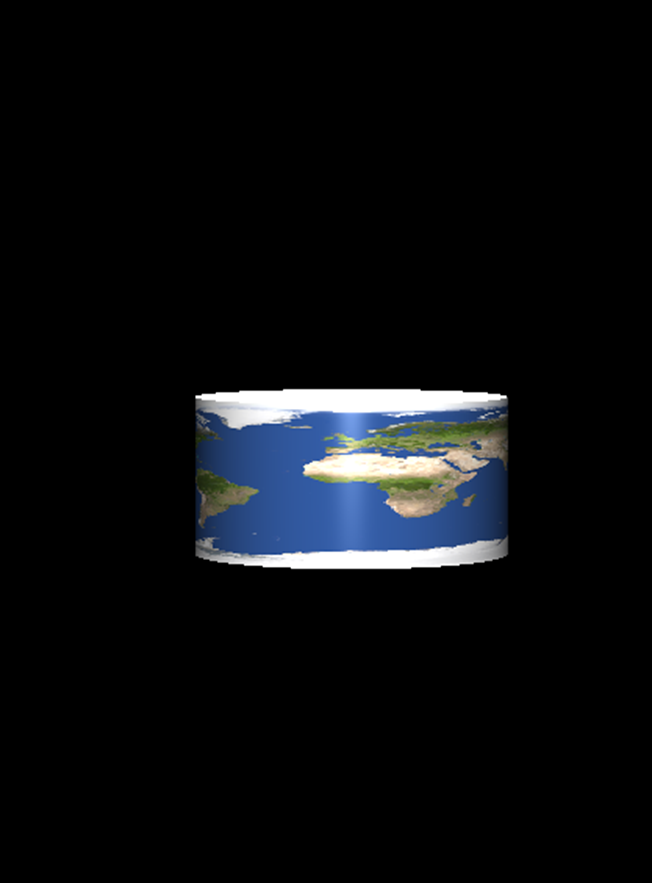
D: canned earth